- Home
- HIROTA Lab.
- Proprietary Technologies
- Introduction of dye and pry test
Proprietary Technologies
Introduction of dye and pry test
2022.10.11

Purpose
The “Dye and Pry Test” makes the soldered joints of BGA(Ball Grid Arrays) visible which were mounted on the PC Board.
It is one of the failure analysis methods which enables to observe the device’s soldered joints surface with the relatively simple equipments.
[Memo] The “Dye and Pry Test” is a destructive test of product.
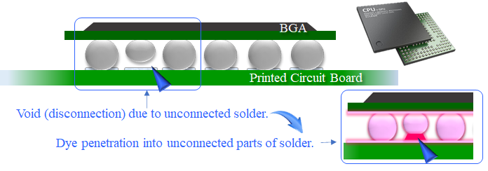
Image of Cross Section
Evaluation Method
Wash the PC Board where BGA are mounted and soak it in the dye, then decompress as it is.
The dye permeates the fine parts such as the gaps of unsoldered joint and the cracks. Pry the device out of the PC Board so that you can observe the dye residue on the unsoldered joint parts.
Merit
You can confirm the soldered joint parts where are invisible from the top by the X-Ray inspection nor by a visual inspection.
It enables you to observe the soldered situation of all BGA at the same time efficiently.
Process of Dye and Pry Test
| (1) Dye Permeation | ||
| Step.1 Removal of the Flux at Mounting and Surface Cleaning |
 [Flux Removing Liquid] |
 [Surfactant] |
| Step.2 Dye Liquid permeates the fine parts |
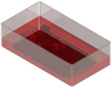 [Dye Liquid] |
 [Decompressing Chamber] |
| Step.3 Removal of Moisture |
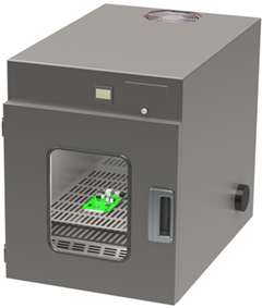 [Drying Chamber] |
|
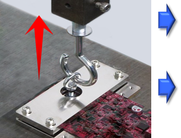
(2) Peeling-off |
||
| Step.4 Peel off BGA out of PC Board with a special tool. |
 |
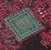 [PC Board Side] 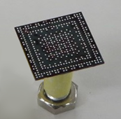 [BGA Side] [BGA Side]Device Size:13㎜×13㎜ Total Number of Balls:367pcs Pitch of Ball:0.5mm minimum |
| (3) Confirmation of Dye Permeation | |||
| PC Board Side | BGA Side | Indication of Observed Dye | |
|
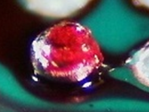
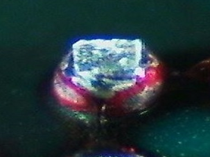
Unsoldered Joint Parts
|
 |
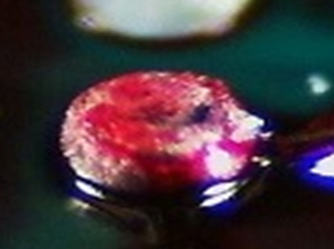 |
It is observed that the dye permeated the contacts(gaps) such as the unsoldered joints and cracks. |
|
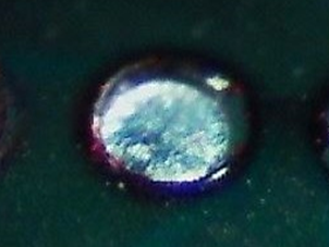
Good Product
|
 |
 |
It is observed that the normal BGA joints are peeled off at the BGA parts or the pad parts of PC Board. |